Driveshaft Measuring Guide
How to Measure for a Driveshaft
Measuring Guide for Proper Fit
Getting accurate measurements is the key to building a driveshaft that performs the way it should. To make the process simple, we’ve created clear diagrams and step-by-step instructions. Follow along and you’ll have the right numbers the first time.
Why Measuring Matters
The most common mistakes come from measuring a vehicle when the suspension isn’t in the right position or when the wrong reference points are used. A few extra minutes spent doing it correctly will save time, money, and frustration later on.
Before You Start
- Make sure your vehicle is secure on jack stands or with the tires on the ground.
- Never measure with the suspension hanging freely.
- Have a tape measure and a small ruler ready.
Step-by-Step Process
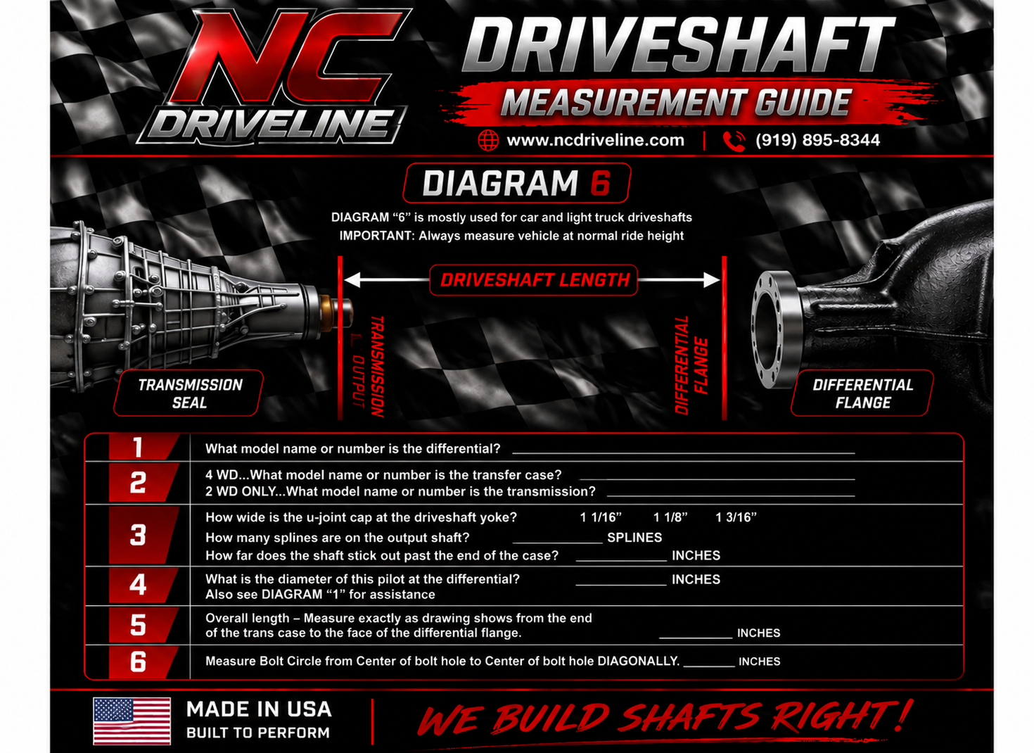
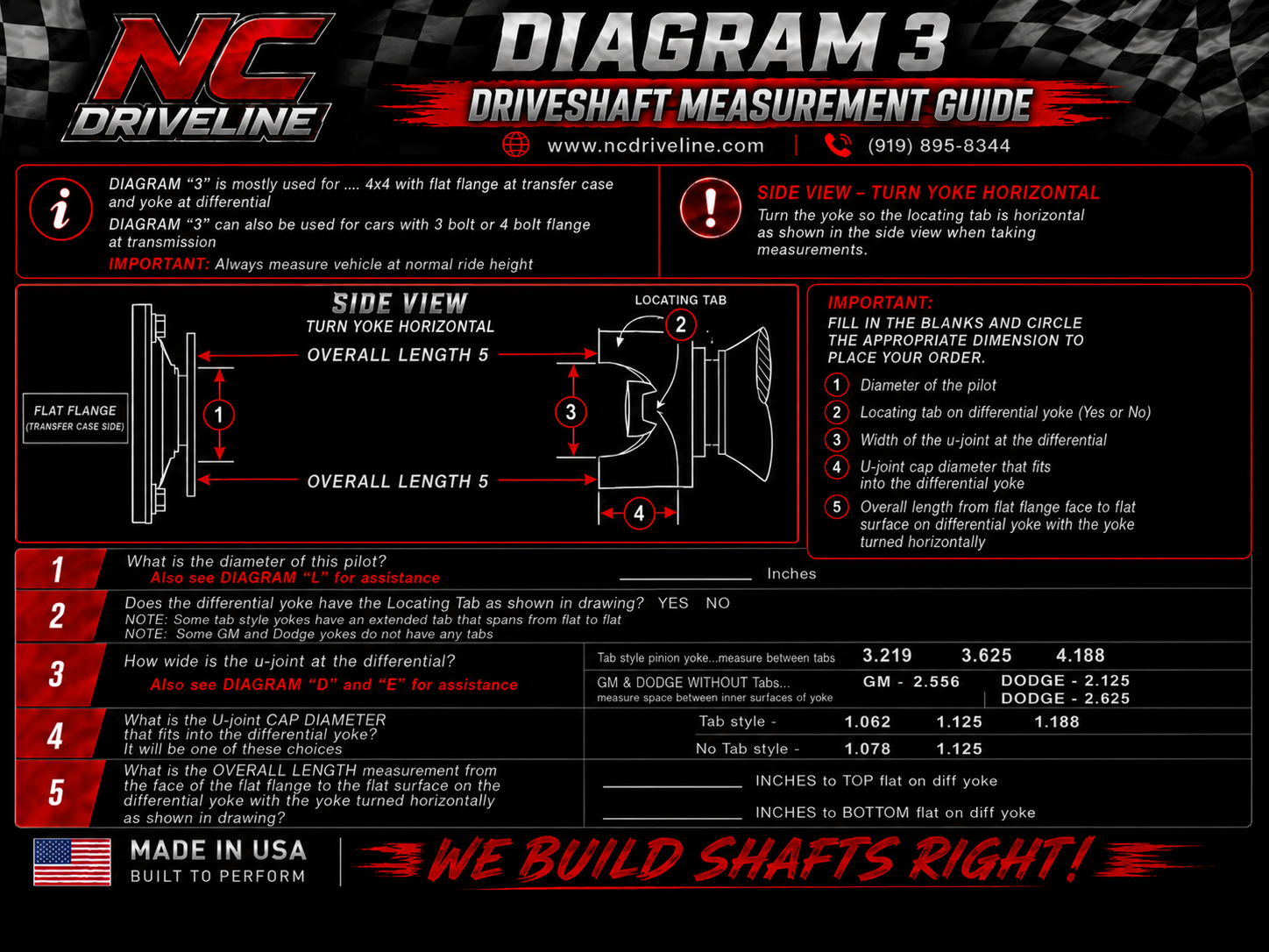
1. Choose the correct diagram.
Browse our set of measuring diagrams and find the one that best matches your setup. Print it out and be prepared to write down every number it calls for. For most hot rods, race cars, and trucks, Diagram B or C will be the right choice.
2. Take your measurements with the suspension loaded.
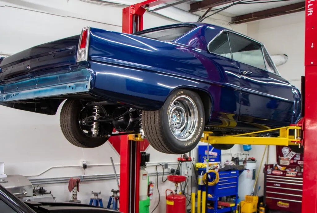
Your measurements should be taken with the rear end supported or the tires on the ground. This ensures the dimensions reflect how the vehicle actually sits and drives. For 4×4 models, both axles need to be supported or resting on the ground.
3. Record all the details.
Each diagram includes blanks and checkboxes for specific options. Don’t skip any — we’ll need a complete sheet to build your shaft or provide an accurate price.
Which Diagram Should I Use?